Introduction
The following tutorial explores one way that we can interact with LCD screens with the help of an Arduino Uno board and RC522 RFID sensor.
Nowadays, Liquid-crystal Display (LCD) screens are everywhere. Found attached to household items, like televisions and refrigerators, to lining streetscapes reporting advertisements and local news – these devices are commonplace in spaces that we inhabit in our everyday lives.
Radio frequency identification sensors (RFID’s) are another common type of sensor. Found in modern smartphones, public transit cards, and inventory management systems, among other uses, RFID’s are helpful when creating a unique identifier system.
In the case below, an RFID imbedded in a public transit card is used to activate the LCD screen to communicate to the rider that their bus is approaching shortly.
Parts List
To complete the steps below, you will need the following parts:
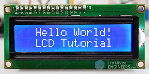
- 16×2 Alphanumeric LCD Display
- RC522 RFID Sensor (found here)
- Arduino Uno board
- Male-to-male wires
- 7 – jumper wires
- 1,000 ohm resistor
- Power source (the example below was powered by connecting to a laptop using a USB cord, though external batteries may also be used.)


The following libraries* are also required:
* For help installing a new .zip library, check out this link from the Arduino website.
Let’s put it together!

Code
The following code may be copied into Arduino IDE (download here) and uploaded to the Arduino Uno board.
// initialize libraries
#include <SPI.h>
#include <MFRC522.h>
#include <LiquidCrystal.h>

// initialize pins
#define RST_PIN         9          // Set RST Pin
#define SDA_PIN          10         // Set SS Pin

LiquidCrystal lcd(7, 6, 5, 4, 3, 2); // RS, E, DB4, DB5, DB6, DB7

MFRC522 mfrc522(SDA_PIN, RST_PIN);  // Create MFRC522 instance

void setup() {
  // initialize digital pin output
 // pinMode(LED_BUILTIN, OUTPUT);

  Serial.begin(9600);   // serial communications with the PC
  while (!Serial);    // If no serial port is opened, do nothing (for ATMEGA32U4 Arduinos)
  SPI.begin();      // Init SPI bus
  mfrc522.PCD_Init();   // Init MFRC522
  delay(4);       // Optional delay
  mfrc522.PCD_DumpVersionToSerial();  // Show details of PCD - MFRC522 Card Reader details
  lcd.begin(16, 2);
}

void loop() {

  // If no new card is present, reset the loop
  if ( ! mfrc522.PICC_IsNewCardPresent()) {
    return;
  }

  // Select one of the cards
  if ( ! mfrc522.PICC_ReadCardSerial()) {
    return;
  }
  // print message onto LCD
  {
    lcd.clear();
    lcd.setCursor(0, 0);
    lcd.print("Bus Hailed... 3 min away...      "); // update this line to desired message
    delay(700);
    Serial.print("LCD is working");
  }

  lcd.setCursor(0, 1);

  // scroll the display four positions to the left every 500ms
  for (int i = 0; i < 23; i++) {
    lcd.scrollDisplayLeft();
    delay(450);
  }
  delay(400);

 // Dump debug info about the card; PICC_HaltA() is automatically called
mfrc522.PICC_DumpToSerial(&(mfrc522.uid));
}
*To change the message that displays on the LCD, update the text that is between the (“…”) from following line:
lcd.print("Bus Hailed... 3 min away... ");Wiring Diagram
Once your code is uploaded, you’re ready to wire everything together! Follow the diagram below to get everything set up and ready to play with:


How to Use
Congratulations on setting up your RFID and LCD sensors!
To use your new setup, simply tap one of the RFID keys (the kit comes with both a plastic card and keychain tag) so it touches the RFID reader. Once activated, the LCD screen will read your desired message and scroll across the screen.